
by Harshita Arora
How to make a digital voltmeter using Arduino
Last Sunday, while I was explaining the basics of electronics and Arduino to my roommate, she challenged me to understand how a voltmeter works and build one from scratch just using the stuff I own already. I accepted the challenge, started hacking, coding, testing, re-coding, and re-testing, and finally I had my voltmeter ready and working by dinner time!
I used Arduino Uno (to collect voltage in analog and to power the LCD), a small LCD screen that I got in my Arduino starter kit (to display the voltage), a breadboard (to connect everything), and jumper wires.
If you’re looking for an easy project to learn electronics, then making a digital voltmeter will be fun. Let’s get started!
The Electric Circuit
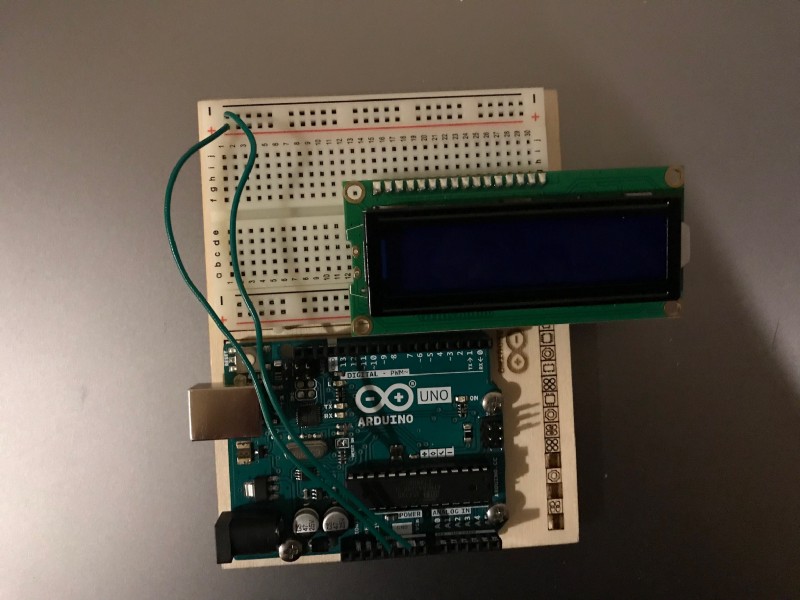
Step 1
Take a breadboard (I used a small one with 30 rows) and connect an LCD screen to it. Then using a wire, connect one wire from the GND pin (ground state) on the Arduino to the negative charge on breadboard, and one wire from the 5V pin to the positive charge. This provides electric current to the columns on the breadboard, which we can now connect to the LCD.
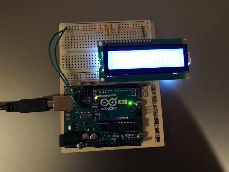
Step 2
Now we’ll connect the pins on the LCD to the breadboard so we can get current to it. Connect Pin 1 of the LCD to a negative charge, Pin 2 to a positive charge, Pin 3 to a negative charge, Pin 5 to a negative charge, Pin 15 to a positive charge, and Pin 16 to a negative charge. Plug in your Arduino to test and see if the LCD turns on!
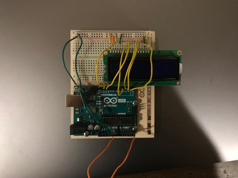
Step 3
Let’s connect the LCD to the Arduino so that we can display the voltage (which we will collect from an analog pin) on the LCD. Connect Pins 4, 6, 11, 12, 13, and 14 of the LCD to any digital pin on Arduino (for example, Pin 2). Then put a wire in the GND and another in an analog pin, like A5. The two wires are now your probe leads.
We’re now done with the electronics/hardware. Let’s move on to the code.
The Code
The code is pretty simple. We just want to collect the analog signal that the Arduino receives at Pin A5 (or any other analog pin) and convert it to digital. We then want to display the results on the LCD screen.
This is the code that you can copy-paste.
#include <LiquidCrystal.h> int Vpin=A5;float voltage;float volts;LiquidCrystal lcd(12, 11, 5, 4, 3, 2);void setup() {Serial.begin(9600);lcd.begin(16,2);}void loop() {voltage = analogRead(Vpin); volts = voltage/1023*5.0; Serial.println(volts);lcd.print(“voltage = “);lcd.print(volts);delay(200);lcd.clear();}What’s going on here?
So we’re first importing the LCD library, then creating a variable named Vpin (which will be the voltage collected from A5). Next, we create two more variables for the voltage, and then a variable of type LiquidCrystal. Finally, we do setup with the Serial monitor (which is a really useful tool in Arduino! Sort of like debug console), convert the analog voltage to digital voltage, and print (display) that value to the LCD screen.
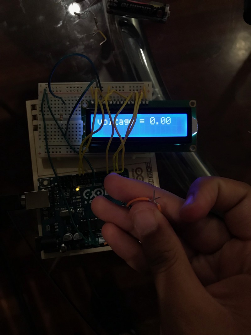
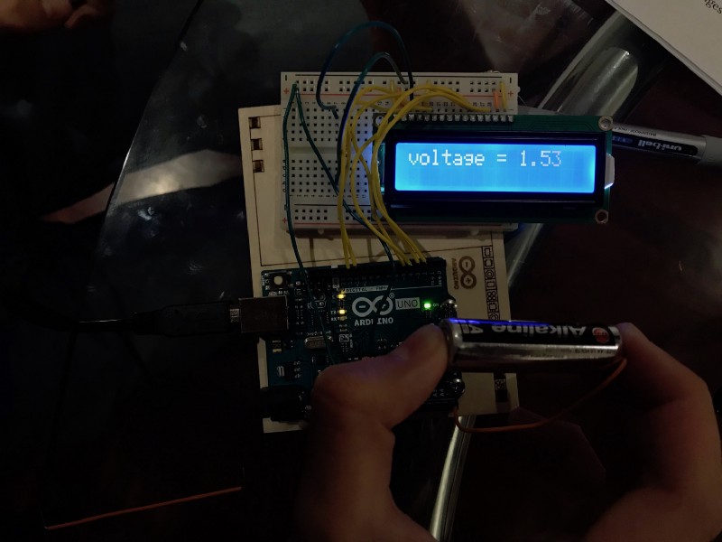
And that’s it! Go and test out various batteries and points! Here are photos from some tests I did:
Also, if you want to make the reading on the LCD more legible, put a 1k ohm resistor in the path to Pin 3 (which is for contrast adjustments). By limiting the electric current flowing to that pin, you’ll improve the contrast of the screen.
Also important note: In this voltmeter, whatever voltage you test will go as a direct input to the Arduino, so you should only test stuff that is in the range of volts that Arduino can safely handle (0–5V). Testing with a 9V battery will fry your Arduino.
Thanks to this video tutorial for helping me figure out the electric circuit. Special thanks to my friends Nick Arner and Johnny Wang for helping me fix stuff. And thanks to Laura Deming for the challenge! :)
More articles and tutorials on electronics/hardware and brain-computer interfaces on the way! :D
If you have feedback to share, feel free to email me at harshita@harshitaapps.com. I look forward to hearing from you!